Establishing a new wavelength band for optical communications
1.Research background
The rapid rise of traffic amount in optical communication networks poses possible wavelength resource exhaustion of the conventionally used C/L bands (11.4 THz).
⇒With the development of quantum dot laser in the 1µmm band, expectations has increased for the exploitation of T/O bands that offers 79 THz worth of bandwidth.
•Extremely wide bandwidth transmission
•? Suitable for short ranged networks or data center networks
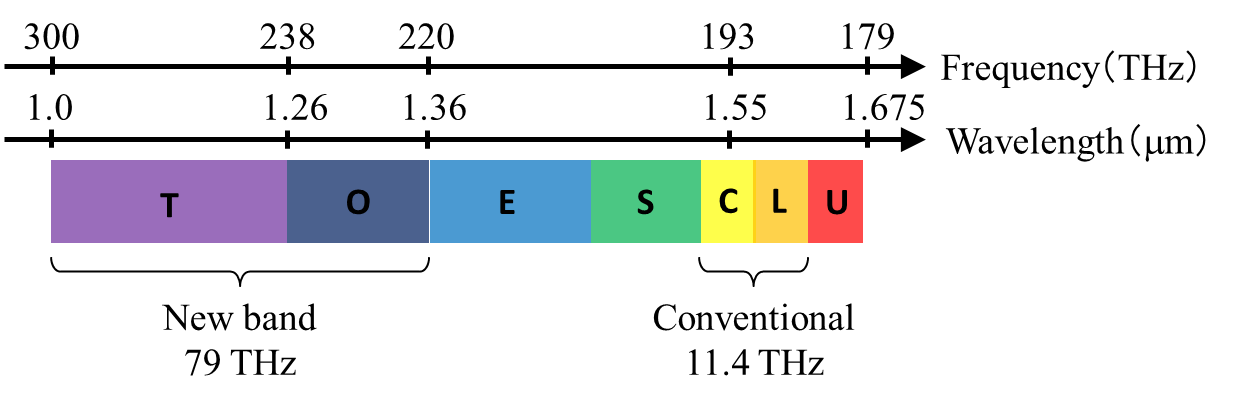
Fig. 1 Wavelength bands used in optical communication
研究目的
Development and enhancement of optical components for establishing a new wavelength band.
(This research is carried out based on a commissioned research of the National Institute of Information and Communications Technology (NICT) entitled ‘Development of Wide Wavelength Range Technologies based on T-band and O-band’, led by Tsuda Laboratory. This commissioned research is also participated by Pioneer Micro Technology, Koushin Kougaku and Optoquest, and comprises these 4 themes shown below.
1.Development of wide bandwidth semiconductor gain chips
2.Development of wide bandwidth and high precision wavelength tunable lasers
3.Development of arrayed waveguide gratings for T and O-band
4.Development of wavelength routing systems utilizing wide wavelength range)
2.High performance arrayed waveguide grating
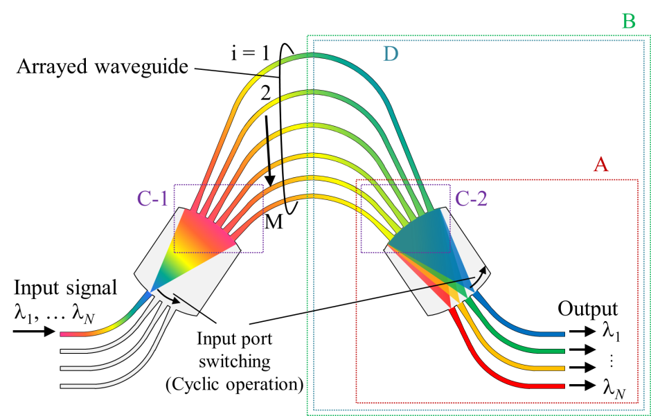
Fig. 2 Conventional AWG structure. We investigate AWG performance enhancements by improving parts in A, B, C, and D
An arrayed waveguide grating (AWG) is an indispensable optical device in wavelength division multiplexing (WDM) communication.
The features required for a high performance AWG are
•Low loss
•Uniform loss difference between channels
•Low crosstalk
•Flat-top passband
•Low wavelength/frequency deviation
•Cyclic characteristic
Sub-topic 1 : Cyclic AWG for extremely wide bandwidth
When designing a cyclic AWG for an extremely large bandwidth such as the T/O band based on the conventional method, the passband peak wavelength deviation becomes highly significant making it impossible to provide cyclic characteristic to the AWG.
The structure of the AWG is shown in Fig. 3. The number of the output ports is doubled to retrieve N wavelengths in a single diffraction order when optical signals enter all possible input ports, and N 2 ? 1 couplers multiplex optical signals from output port 1~N/2 with signals from output port N/2+1~N
We designed a 10-ch, 6.4 THz spaced cyclic AWG. Fig. 4 shows the transmission spectrum for input port N. On the left side of the passbands resulted from output ports 1~N/2 are the passbands resulted from output ports N/2+1~N. Switching the input port from N to 1 will shift the passbands to the left side, which confirms that cyclic operation is possible. The largest deviation is 26% of the channel spacing in a frequency grid
The structure of the AWG is shown in Fig. 5. We employ an interleaved chirp onto the arrayed waveguides, where the center wavelength of the even numbered waveguides is shifted N times of the channel spacing from the center wavelength of the odd numbered waveguides to produce an identical neighboring light pattern. By adjusting the center wavelength of the even numbered waveguides, we can match the diffraction order number of the even and odd numbered waveguides, making it possible to largely reduce the peak wavelength deviation.
We designed a 10-ch, 30 nm spaced cyclic AWG. Fig. 6 shows the transmission spectrum for input port 1. On the right side of the passbands resulted from odd numbered waveguides are the passbands resulted from even numbered waveguides. Switching the input port from 1 to N will shift the passbands to the right side, which confirms that cyclic operation is possible. The largest deviation is 2% of the channel spacing in a wavelength grid.
Light scattering at the gaps between arrayed waveguides near the boundary of arrayed waveguides and slab waveguide is the primary cause of loss.
Fig. 7(a) shows the multi-step taper structure. We achieved loss reduction by optimizing W and L. The results are shown in Fig. 7(b). Transmittance is improved approximately 1.5 dB for all arrayed waveguides compared to waveguides with normal tapers.
The structure of the star couplers in an AWG leads to lower transmittance the further the output port position is from the center.
Fig. 8(a) shows the multi-step taper structure. We achieved loss imbalance reduction by optimizing W and L. The results are shown in Fig. 8(b). Loss imbalance is reduced to as low as 0.36 dB, which is approximately 1.0 dB better compared to waveguides with normal tapers.
Doubling the free spectral range (FSR) is well-known method for reducing loss imbalance between channels of an AWG.
We designed a 32-ch, 50 GHz spaced AWG. The loss imbalance is reduced as much as 4.0 dB compared to normal AWG. The maximum and minimum loss of each output port of the AWG is shown in Fig. 10.
A wavelength tunable laser is an essential component in a WDM network. In particular, it is an indispensable component for a router that uses AWGs to control the wavelength route.
•The peak wavelength deviation is largely due to the conventional AWG using multiple diffraction orders to throughout cyclic operation
⇒We propose AWG structures that is able to operate cyclically using only a single diffraction order
•Large peak wavelength deviation reduction
Sub-topic 1-1 : AWG that combines an Nx2N AWG with 2x1 couplers
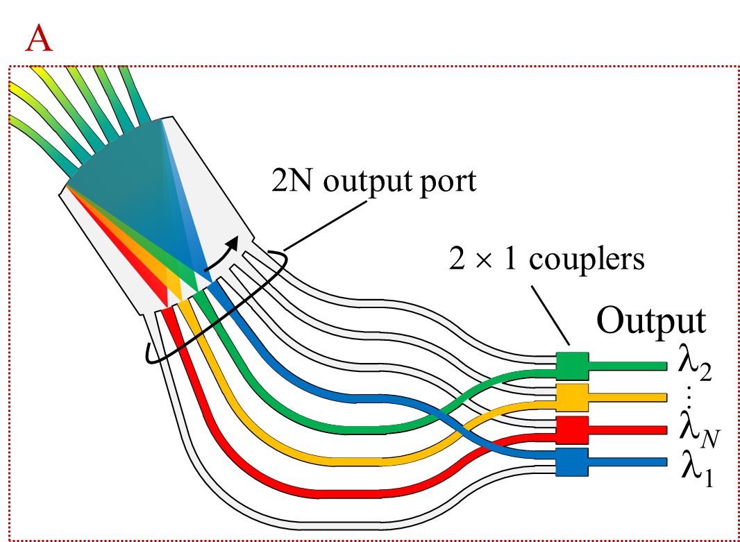
Fig. 3 Structure of AWG that combines an Nx2N AWG with 2x1 couplers
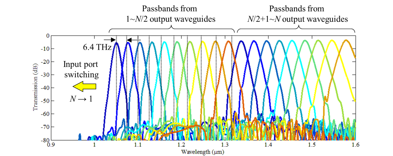
Fig. 4 Transmission spectrum of the 10-ch, 6.4 THz spaced cyclic AWG. Dotted lines show 6.4 THz frequency spacing.
Sub-topic 1-2 : AWG with interleaved chirp waveguides
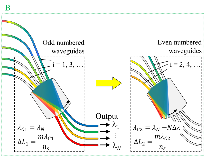
Fig. 5 Structure of AWG with interleaved chirp waveguides
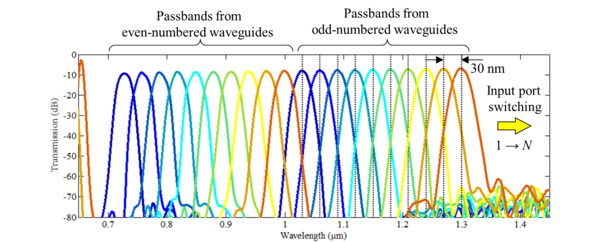
Fig. 6 Transmission spectrum of the 10-ch, 30 nm spaced cyclic AWG. Dotted lines show 30 nm wavelength spacing
Sub-topic 2 : Using multi-step taper waveguides for high performance AWG
Sub-topic 2-1 : Low loss AWG
⇒To reduce loss, we proposed employing multi-step taper structures on the boundary of the 1st slab waveguide and arrayed waveguides.
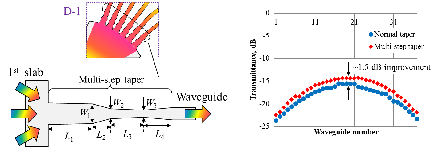
Fig. 7 (a) Multi-step taper structure. (b) Transmittance of each arrayed waveguides (normal and multi-step tapers).
Sub-topic 2-2 : AWG with uniform peak transmittance
•Produces loss imbalance between channels
⇒We proposed employing and optimizing multi-step taper structures on the boundary of the 2nd slab waveguides and arrayed waveguides to reduce loss imbalance between channels
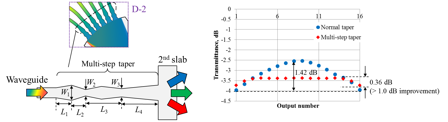
Fig. 8 (a) Multi-step taper structure. (b) Transmittance of each output waveguides (normal and multi-step tapers).
Sub-topic 3 : Reducing loss imbalance in a cyclic AWG using interleaved chirp waveguides
•However, doubling the FSR makes cyclic operation impossible
⇒We propose an AWG that functions cyclically even with a doubled FSR by employing interleaved chirp on the arrayed waveguides.
•? A cyclic AWG with low loss imbalance is realizable
Fig. 9 shows the operating principle of the AWG. Neighboring peaks are produced at half of the FSR by the interleaved chirp waveguides to enable cyclic operation.
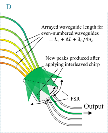
Fig. 9 Principle of the cyclic AWG using interleaved chirp waveguides.
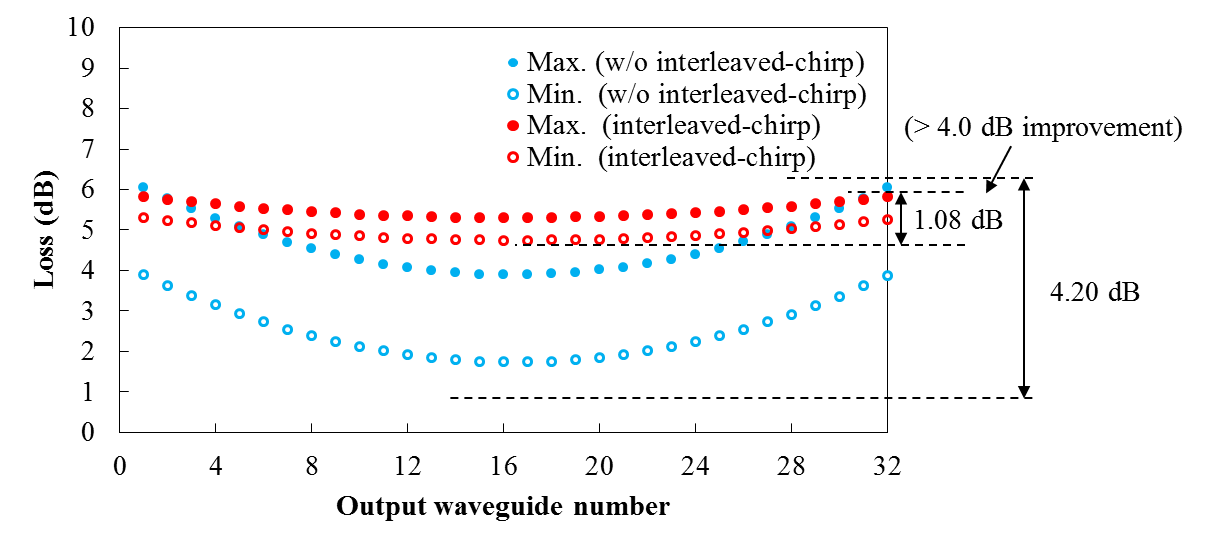
Fig. 10 Maximum and minimum loss for each output port of the AWG using interleaved chirp waveguides.
Sub-topic 4 : Wavelength tunable external cavity laser using AWG
•However, there is still few developments on a wavelength tunable laser in the T band
⇒We propose a wavelength tunable external cavity laser that utilizes the demultiplexing properties of the AWG.
•Wavelength tuning is performed by changing the input port of the AWG.
•The wavelength spacing of the AWG is 400 GHz.
•The gain chip is an InGaAs quantum dot gain chip with an oscillation wavelength of 1140 nm.
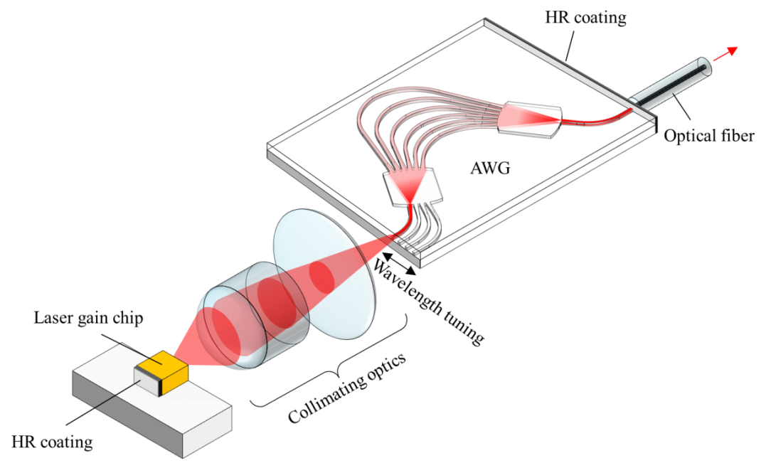
Fig. 11 Structure of the tunable external cavity laser with AWG.
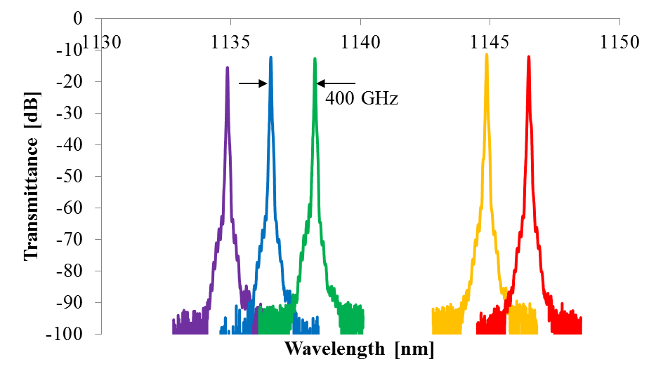
Fig. 12 Oscillation spectrum control of the external cavity laser
(4)Achievements
(a).Journals
[]
(b).International conferences
[1]
Hideaki Asakura, and Hiroyuki Tsuda,
''Loss Uniformity Improvement of Arrayed-waveguide Grating Router using Interleaved Chirped Array,''
European Conference on Integrated Optics (ECIO 17th) and MicroOptics Conference (MOC 19th), P025, Nice, France, Jun. 24-27, (2014).
[2]
Nazirul Afham bin Idris, Hideaki Asakura, and Hiroyuki Tsuda,
“Extremely Wide-bandwidth Cyclic Arrayed Waveguide Grating for Waveband Routing on T-band and O-band,”
Integrated Photonics Research, Silicon, and Nanophotonics 2014, JT3A.29, July 13-16, San Diego, U. S. A. (2014)
更新情報